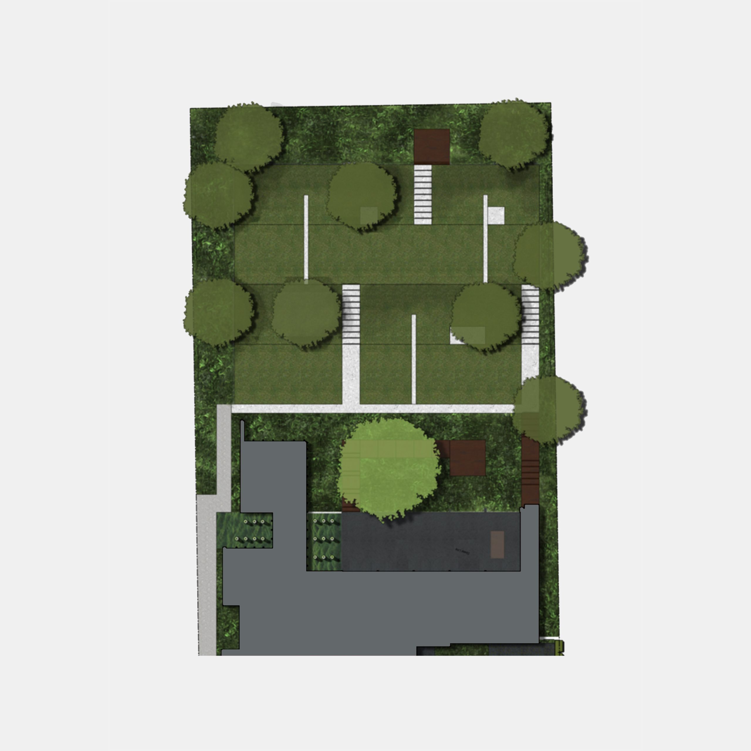
A secluded and restrained response to a suburban street, with contrast in form and function.
Diagram
CHAPTER
01
01 (a)
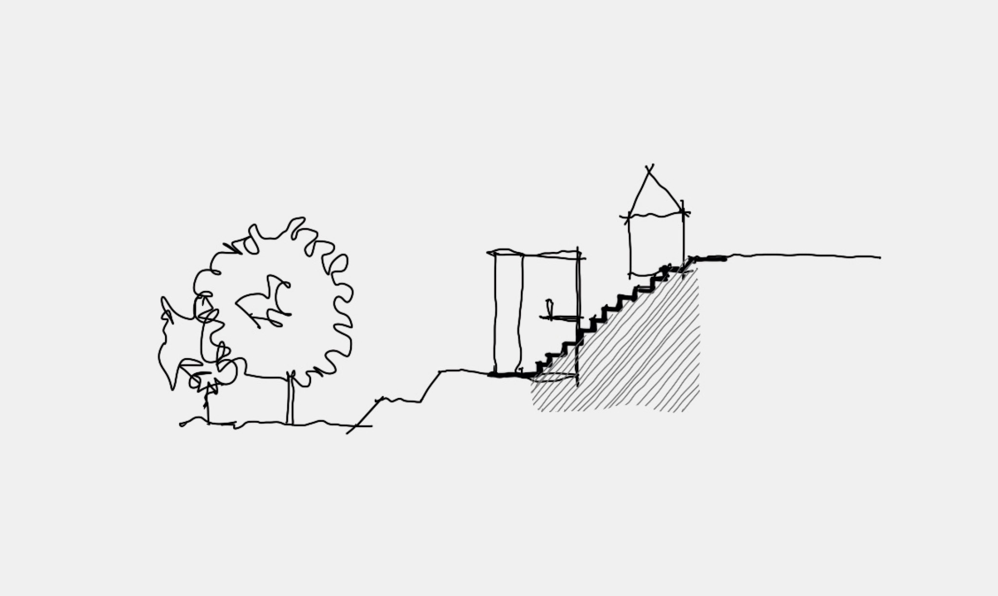
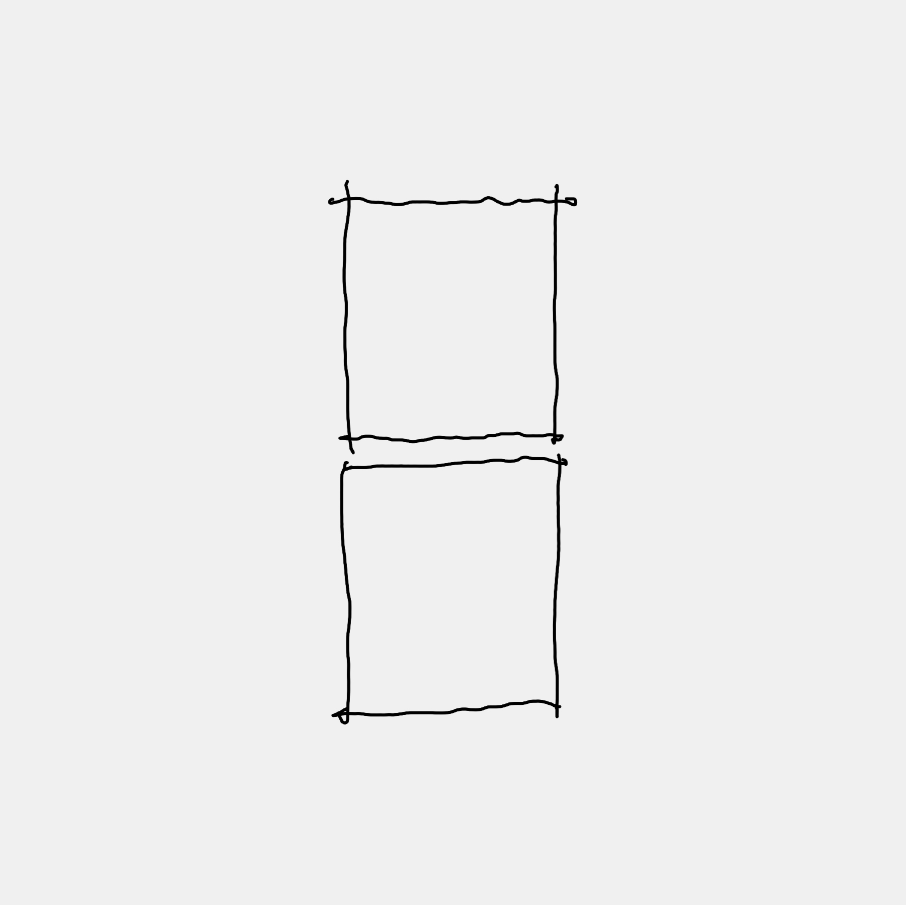
This section diagram provides the basis for the Concept Design.
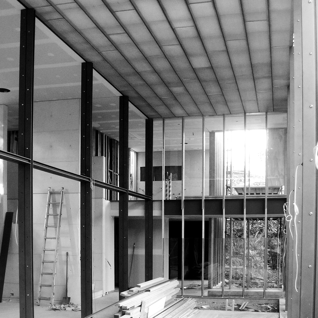
We solved the challenge of a steep site where the land falls away quite significantly. For context, many Brisbane houses that are built on ridge roads have extensions along the same plane as the original Queenslander, so by the time you get to a larger footprint of a house (such as the main living area) you are miles up in the air. Taringa House is different.
01 (b)
Situated on a traditional Brisbane ridgeline Terrace, Taringa house was originally a four-room worker’s cottage and is now juxtaposed but contrasting building forms.
At one plane, the cottage retains its principal role of addressing the historical character of the street. On another plane, the addition faces and connects to the rear of the site, celebrating the natural landscape. This includes a creek at the rear of the property and magnificent Jacaranda as a focal point.
01 (c)
Here, the new house is something that turns its back to the street, focuses internally and takes advantage of the natural habitat. This philosophy then starts to define everything that happens, the functionality.
Functions of the old and new remain distinct; public and private, street and backyard, visitor and family, entry and living. The pragmatic cottage and font yard retains much of its historical detail. Whilst the new addition, right down to the landscaping is architectural, composed and structured.
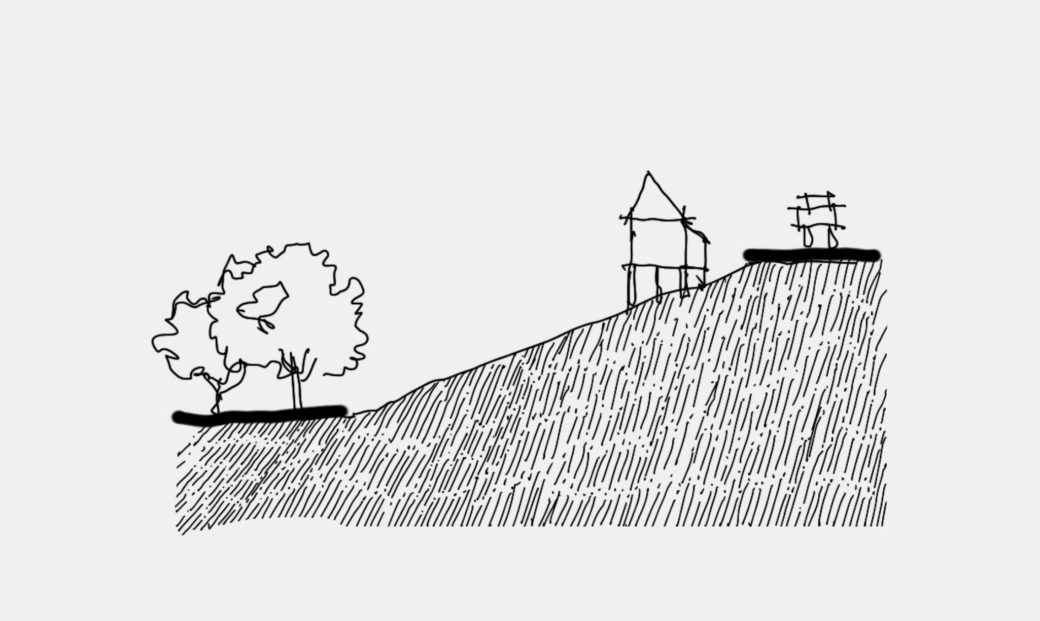
What’s missing in this diagram is the connection to the ground, so the next diagram is a transformation of our original idea.
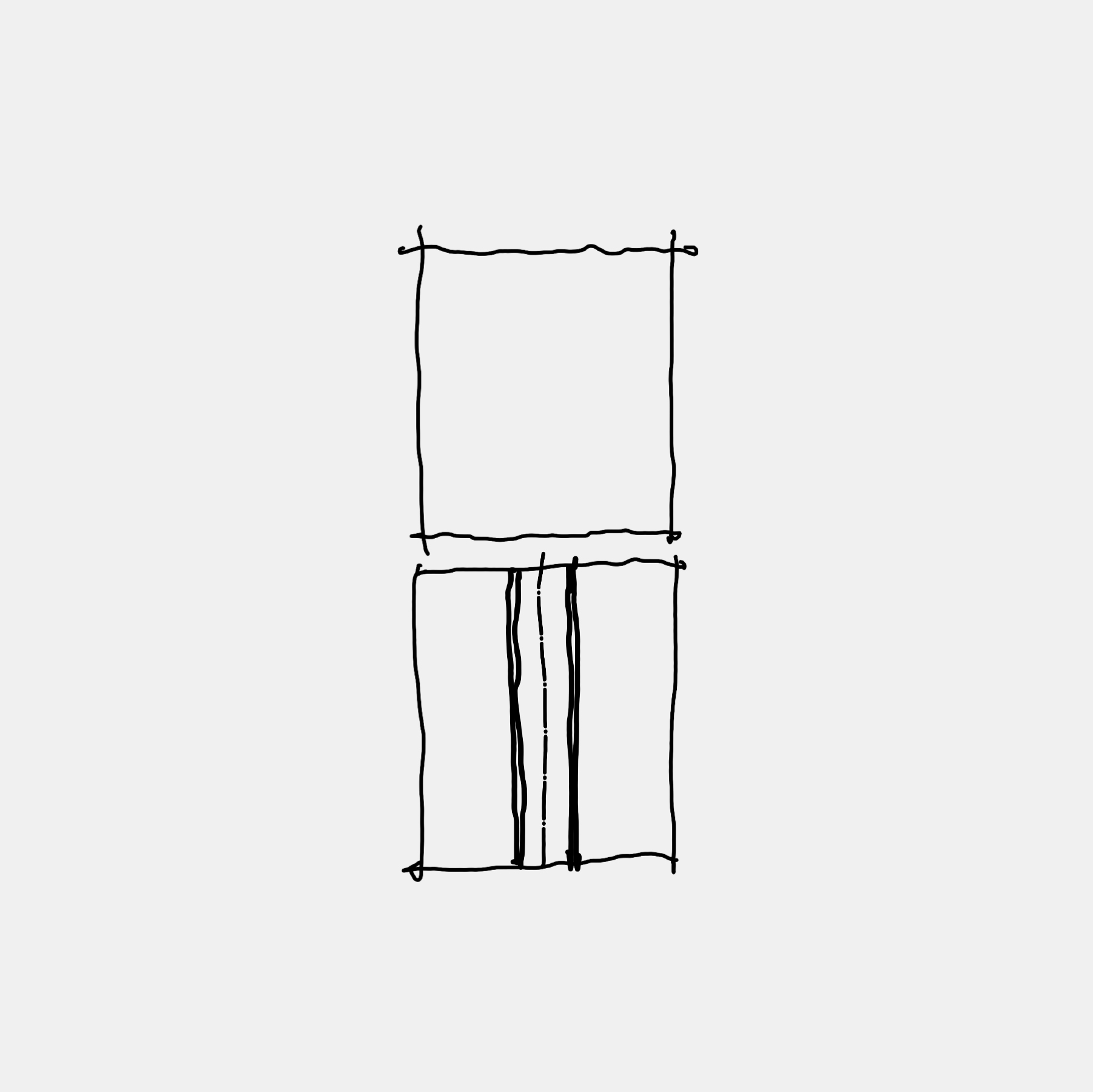
01 (d)
We looked at what needs to happen to connect to the land. The built form needed to be at the level of the land at the back of the site. That’s where we came up with this transformation, the shearing of two spaces so they appear like bookends.
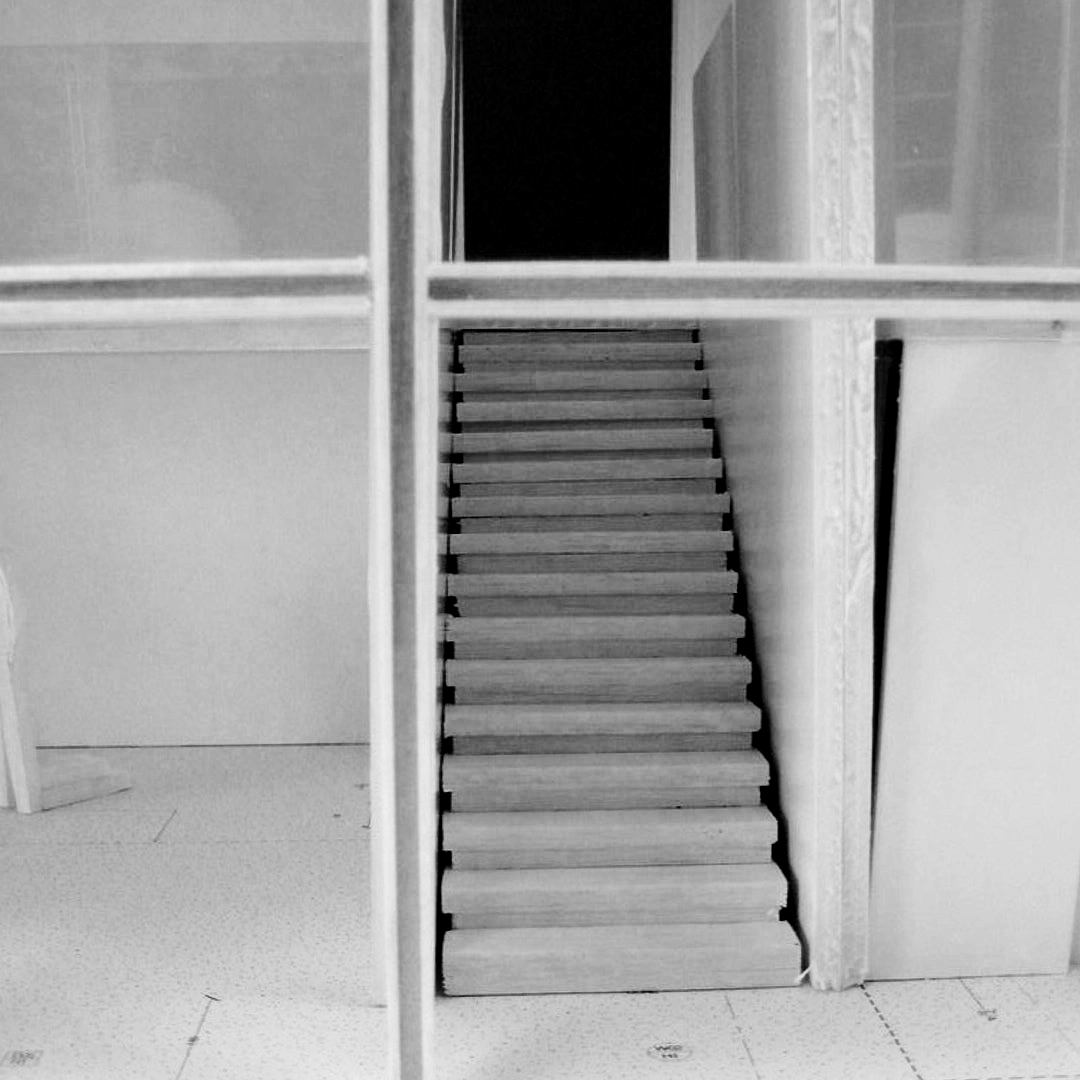
That started to generate the idea for the main design feature. A hero of the interior is a central circulation spine that creates a ceremonial entrance from the existing cottage, drawing the eye to natural habitat. The contemporary addition then provides ground connection, and a sense of calm is achieved through its inherent simplicity.
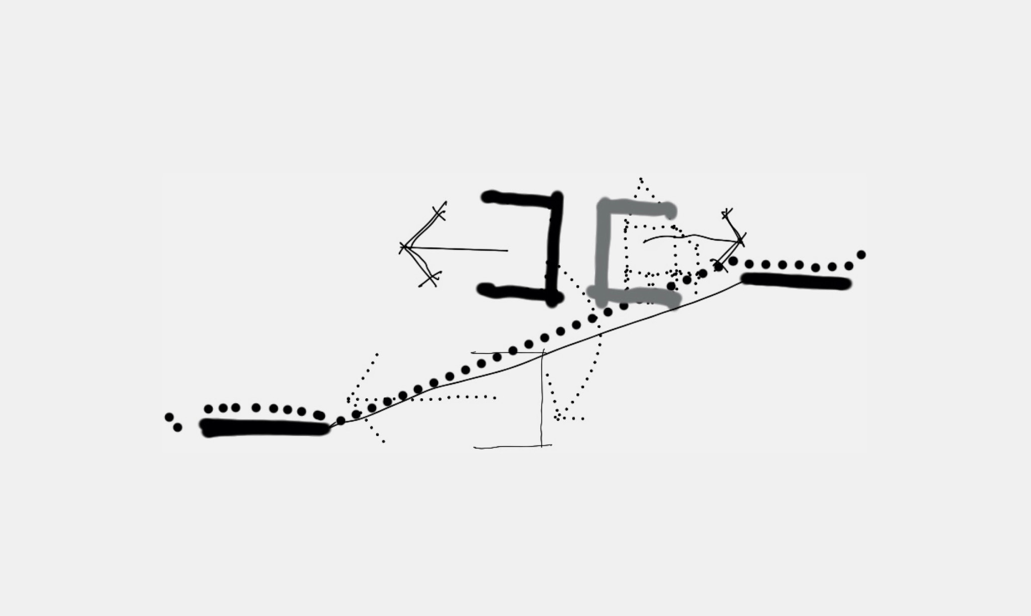
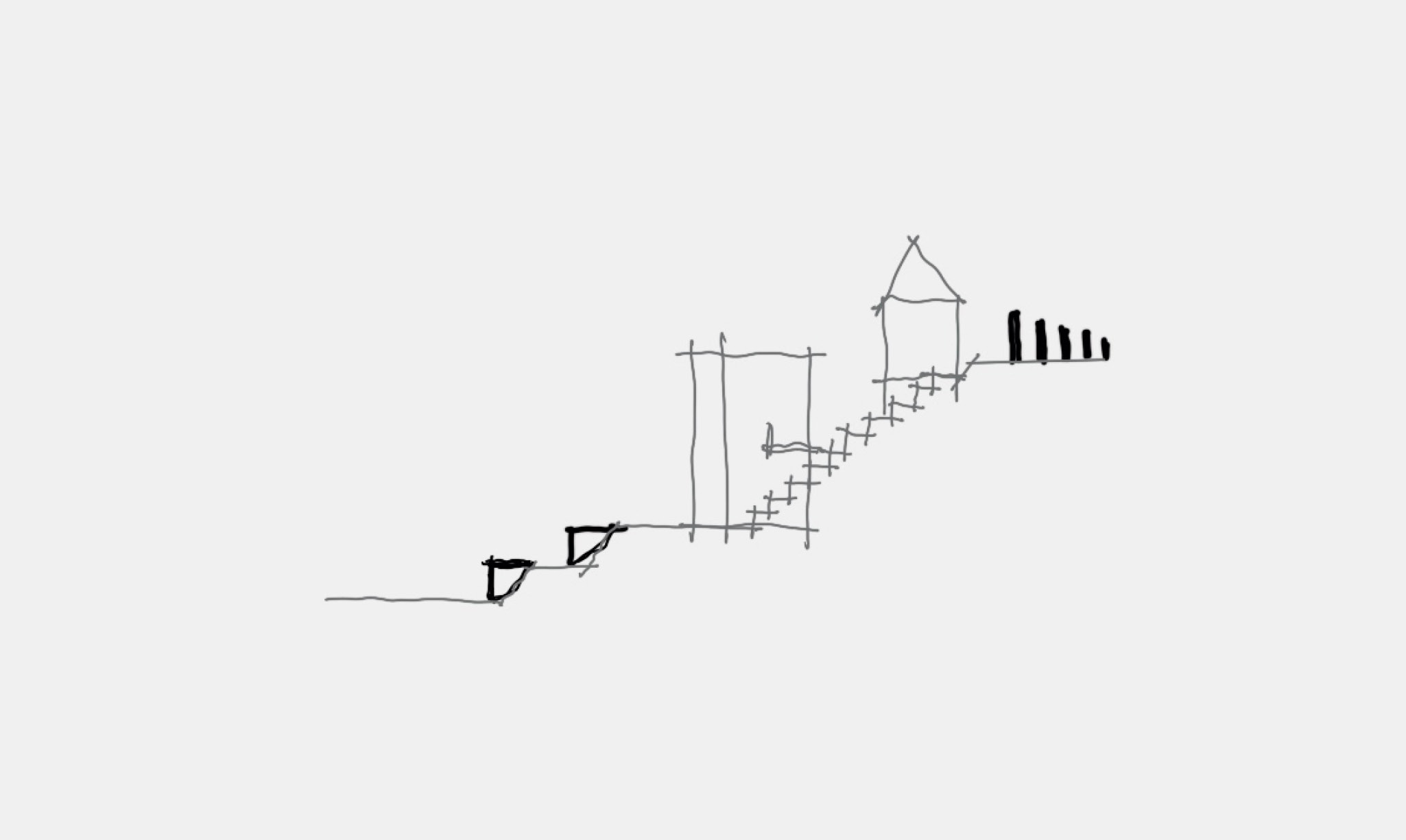
01 (e)
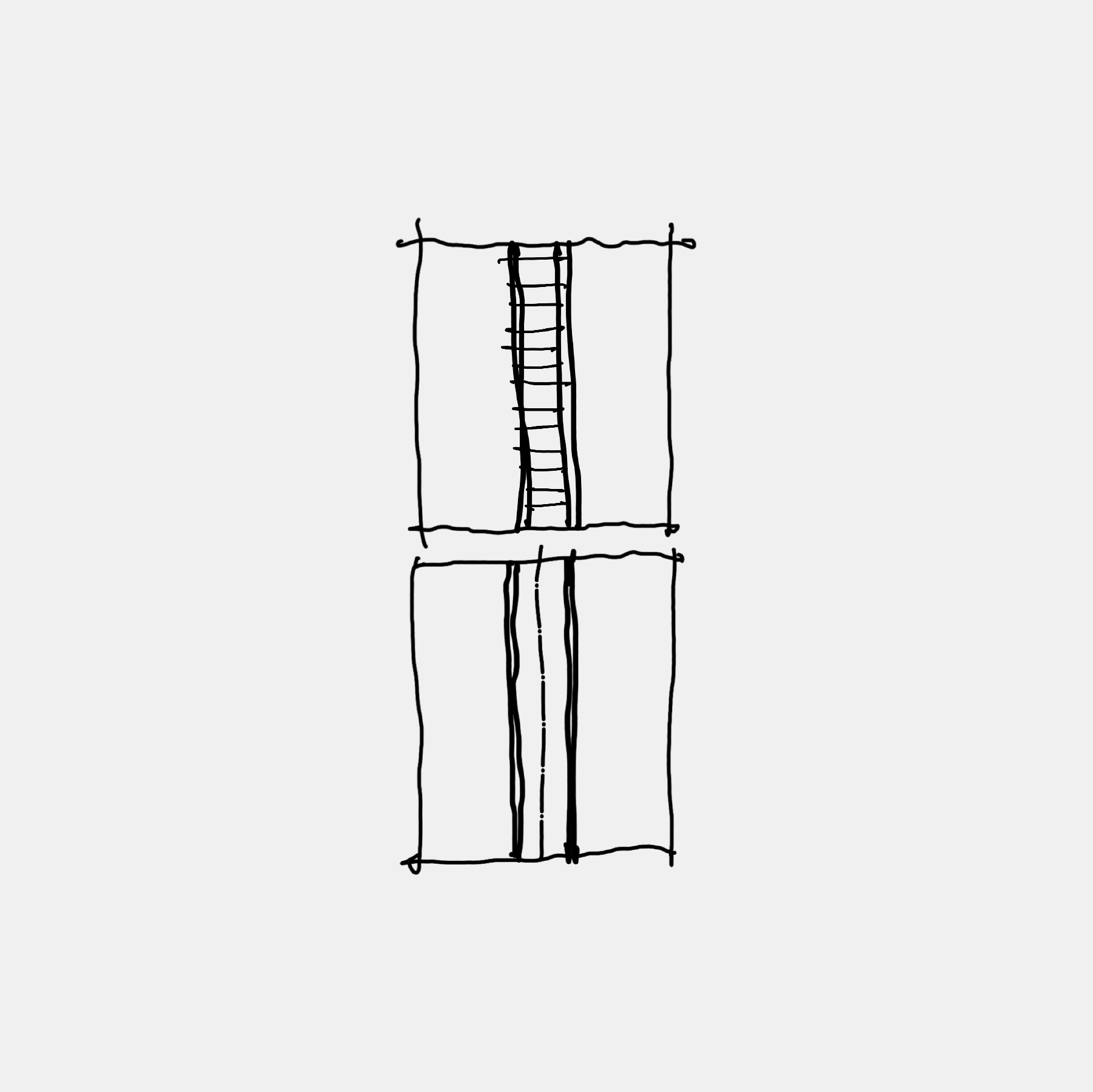
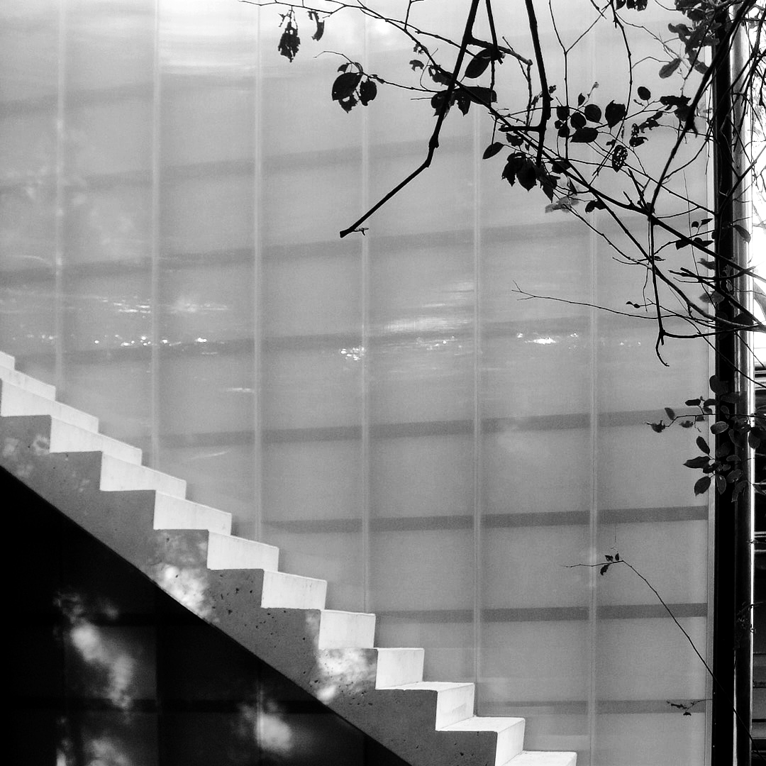
This diagram in an evolution of diagram 4. The sheared arrangement enables the double height glazed living area to open out to the sub-tropical vegetation of the backyard, blurring the boundaries between inside and out.
With longevity and comfort in mind, a refined palette with warm timber and statuario marble pair well with robust, low-maintenance materials such as copper cladding and off-form concrete.
01 (f)
To blend into the environment, the concrete anchoring the new house starts to permeate the landscape through cascading terraces down the hill to the rainforest, like ruins. The same design principle of rhythm is used in the front garden where stumps, the last remaining element of the Queenslander – aka ruins of a Queenslander – permeates the landscaped entry to Taringa House at street level.
Space
CHAPTER
02
02 (a)
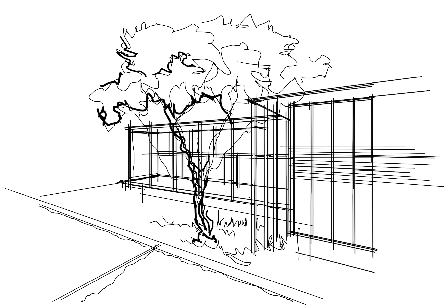
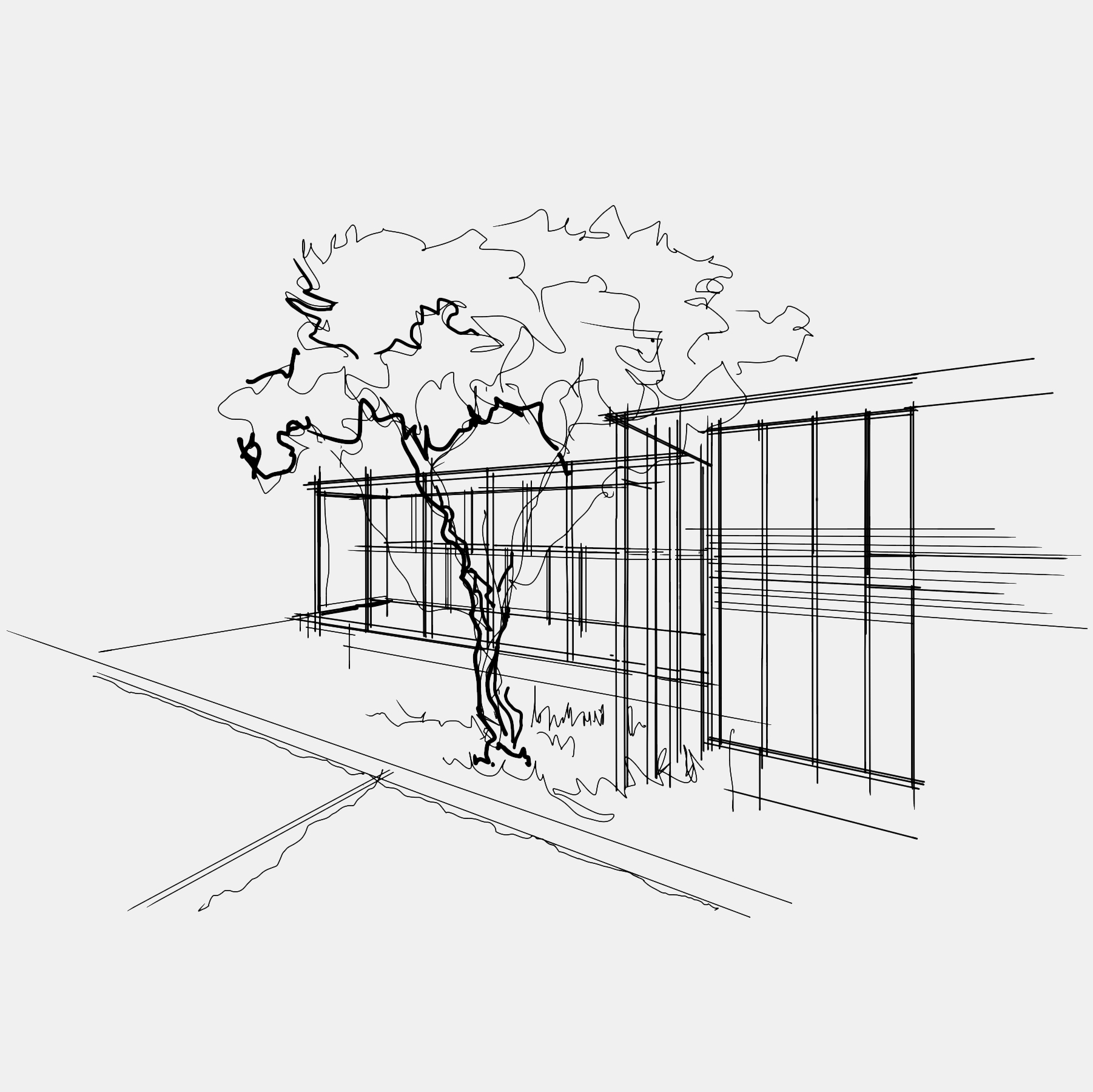
Landscaping Generated from the diagram space is about a holistic connection/relationship to subtropical garden and the Jacaranda tree to which the house is cantered. The cascading garden and tree form inspired the concept of creating space that contrasted in scale to modest Queenslander, This is an early GARDEN STUDY that was used to develop from the diagram.
02 (b)
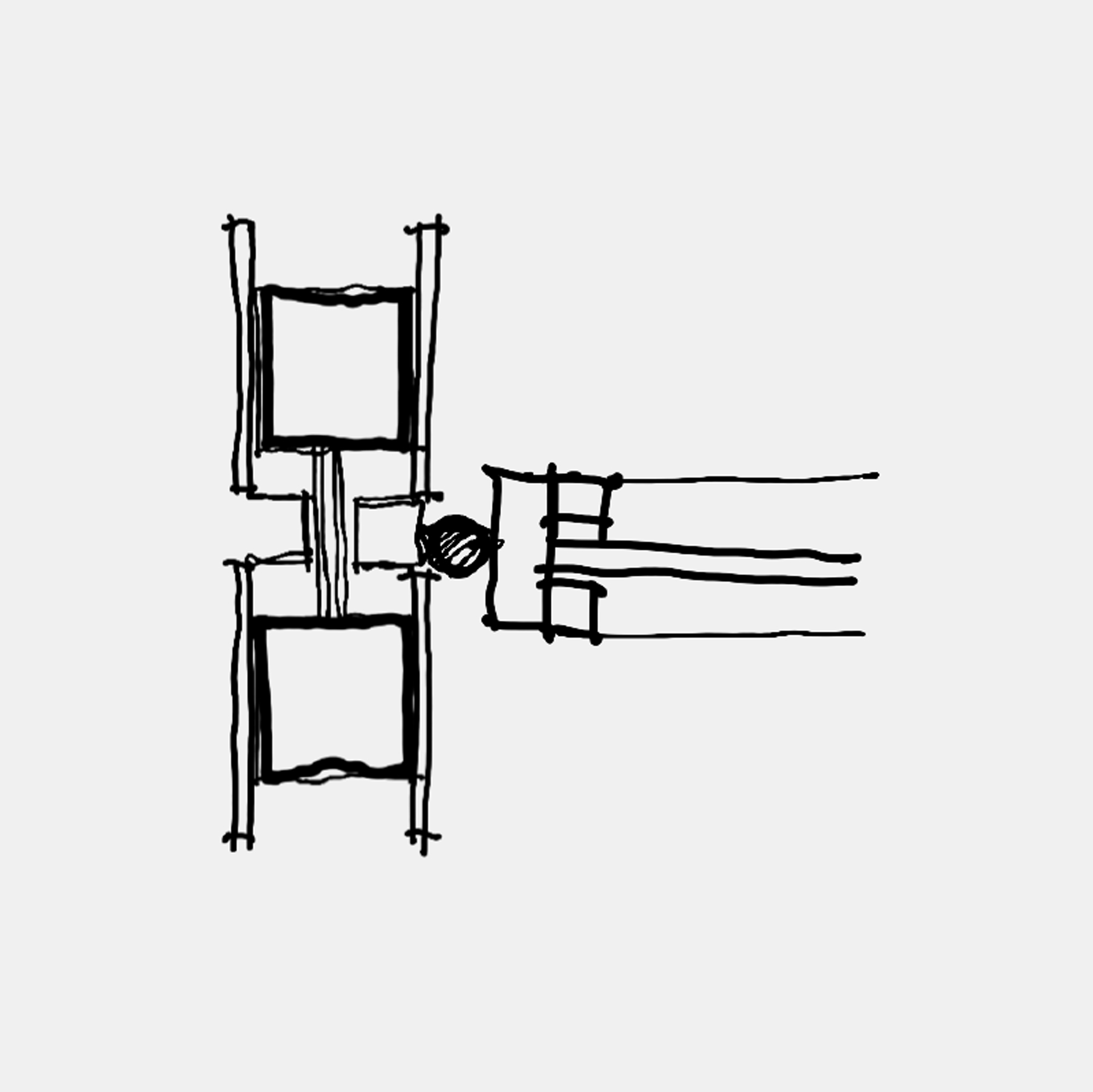
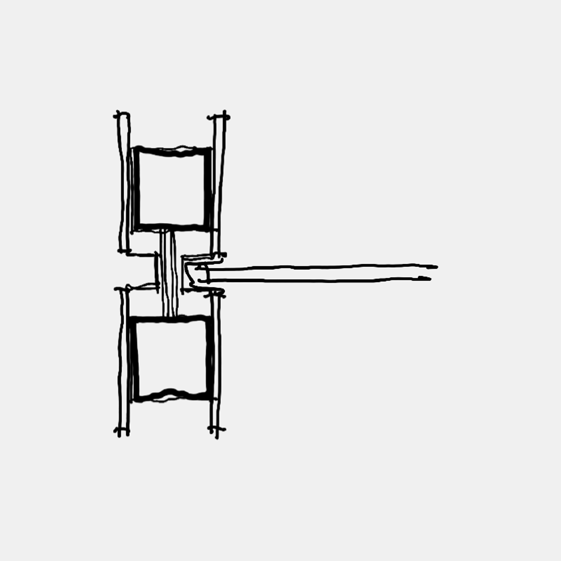
Thin columns surrounding the tree Early sketch of how the rear of the house wraps around the jacaranda. The study was about generating a rhythm of tall slender “Thin Columns” emulating the slender proportions of “branches in the tree”
Here space in generated a contrast to the Queenslander and to reinforce connection to the rainforest.
02 (c)
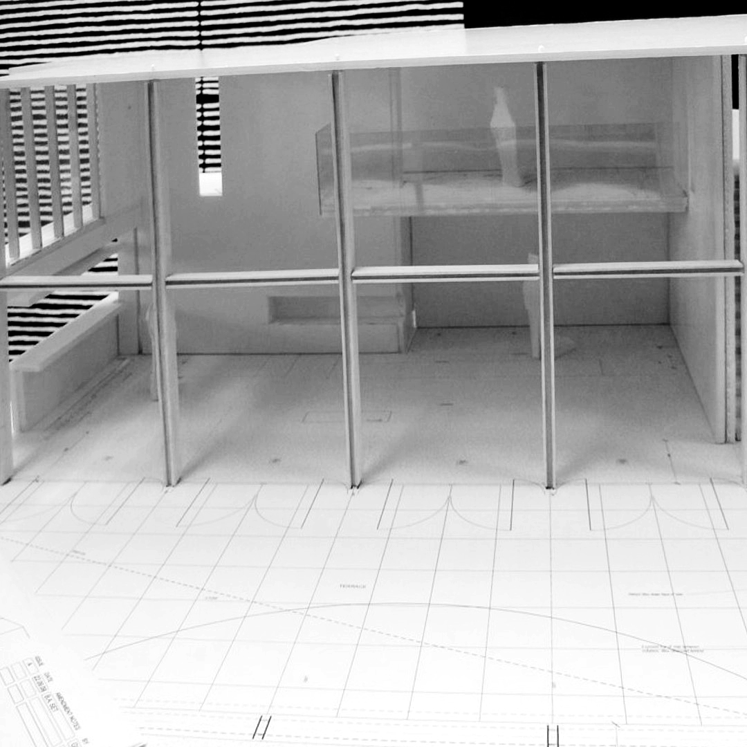
Glass Facade The concept of a two-storey façade that would be 15m long and 5.2 high connecting interiors to the landscape separated separated by the ”Thin Column Apron” is investigated
02 (d)
Model Study 01 Early models study of the glass curtain wall and its relationship to the two-storey volume.
02 (e)
Model Study 02 Early models study of the glass curtain wall and thin column detail and connecting spine circulation. The idea of articulation of steps to wall is considered.
Detail
CHAPTER
03
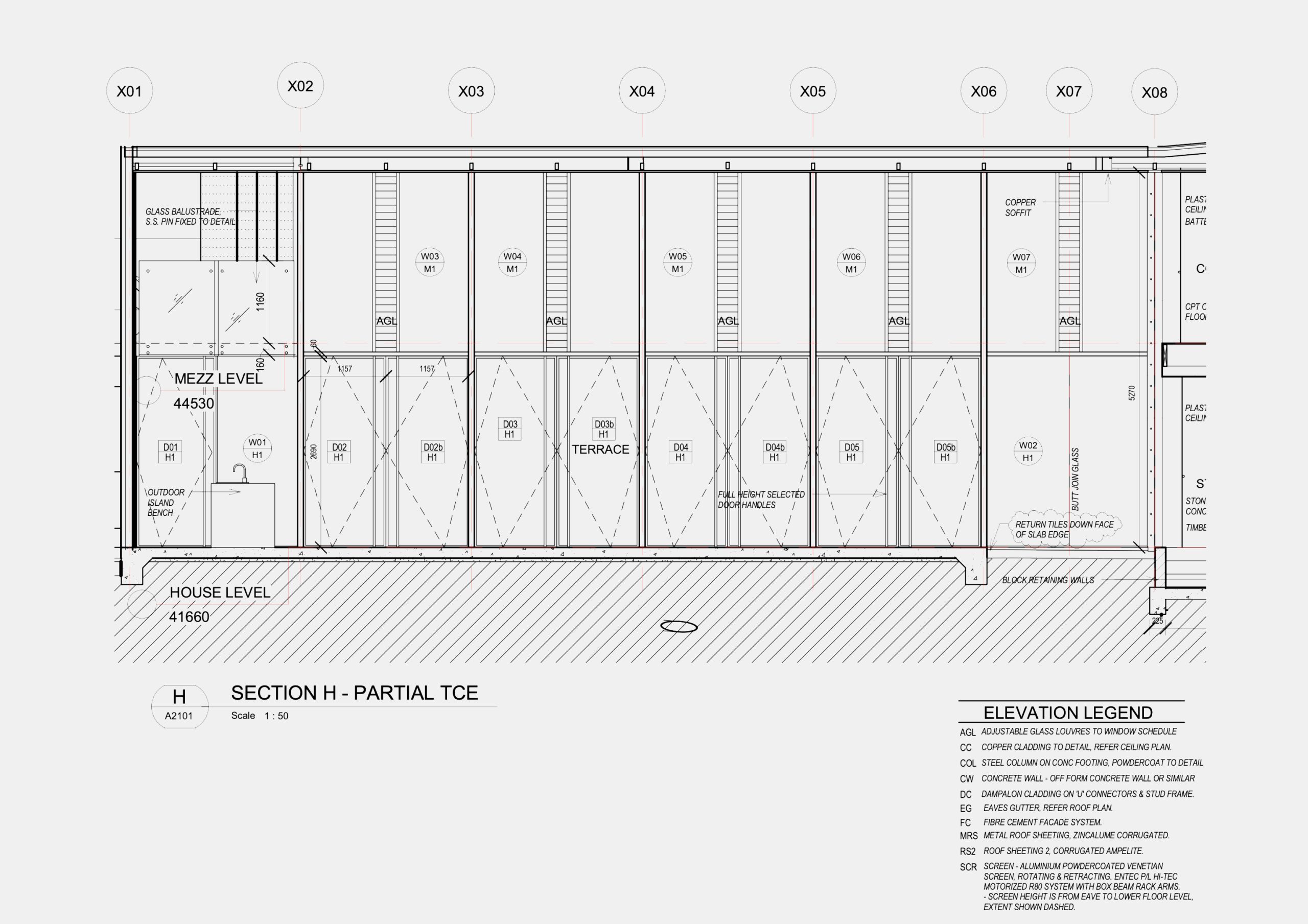
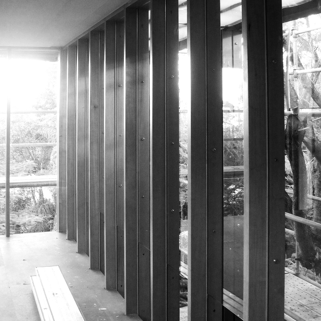
Facade Detail
03_1 (a)
Facade Detail
Typical Panel Setout based on 2.4m ceiling height. Primary panel now generated by 2.4 x 2.4 square divisible by 4n.o 600 panels which is the typical timber glazing grid and 6 x 400mm which is the typical copper panel setout
03_1 (b)
Facade Detail
Façade becomes an assembly (array) of typical panels
03_1 (c)
Facade Detail
Typical double height panels (2 panels) between columns
03_1 (d)
Facade Detail
Door handles generate rhythm
03_1 (e)
Facade Detail
High level ventilation mullions follow door handle setout
03_1 (f)
Facade Detail
Curtain wall facade final proportions and detail resolved
03_1 (g)
Facade Detail
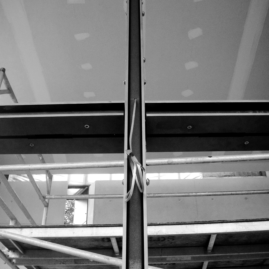
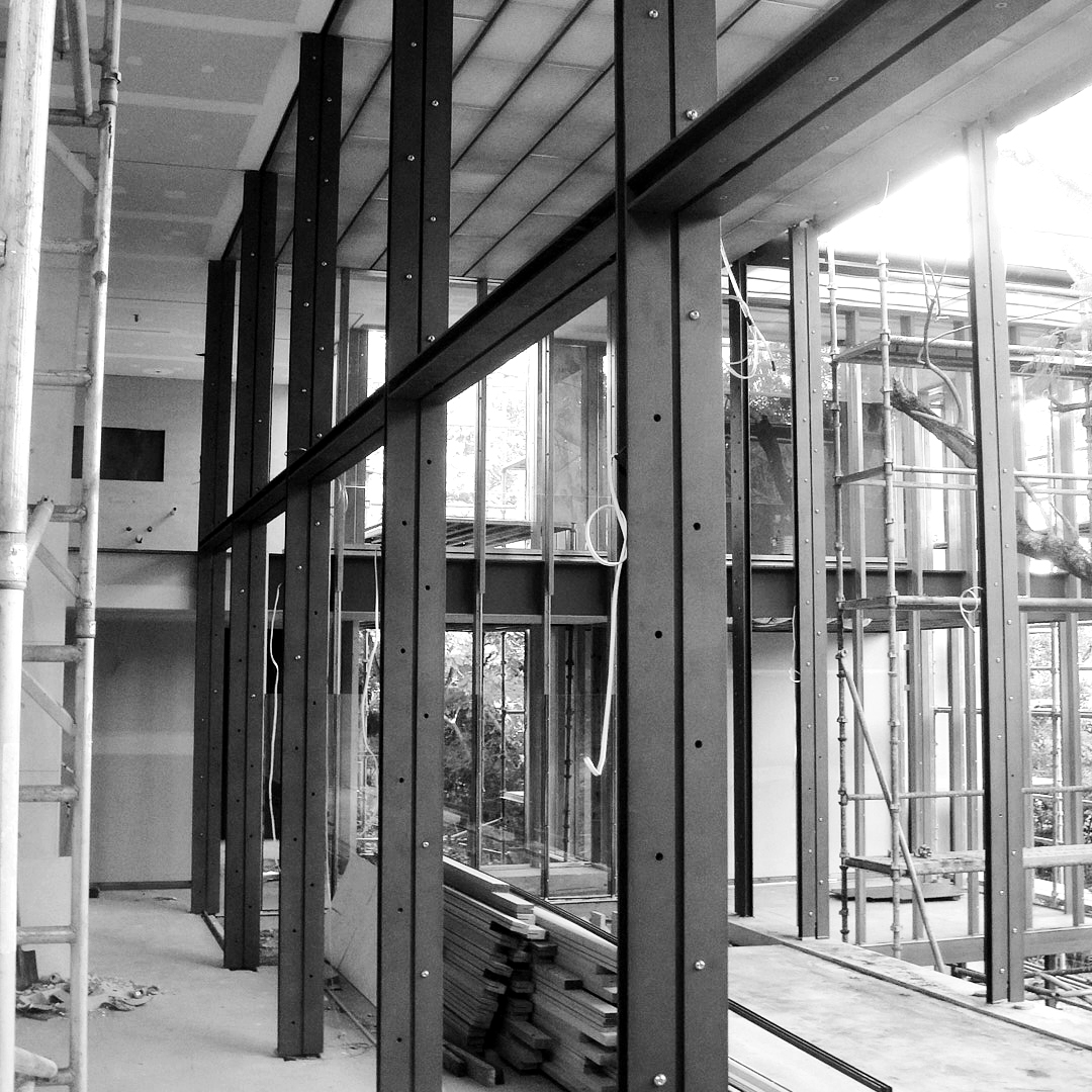
Construction Skeletal structure of façade incorporating Thin Column detail
03_1 (h)
Facade Detail
Construction Thin Column resolution
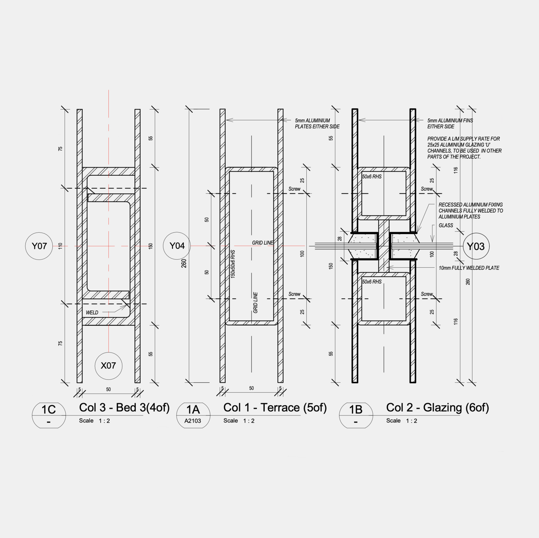
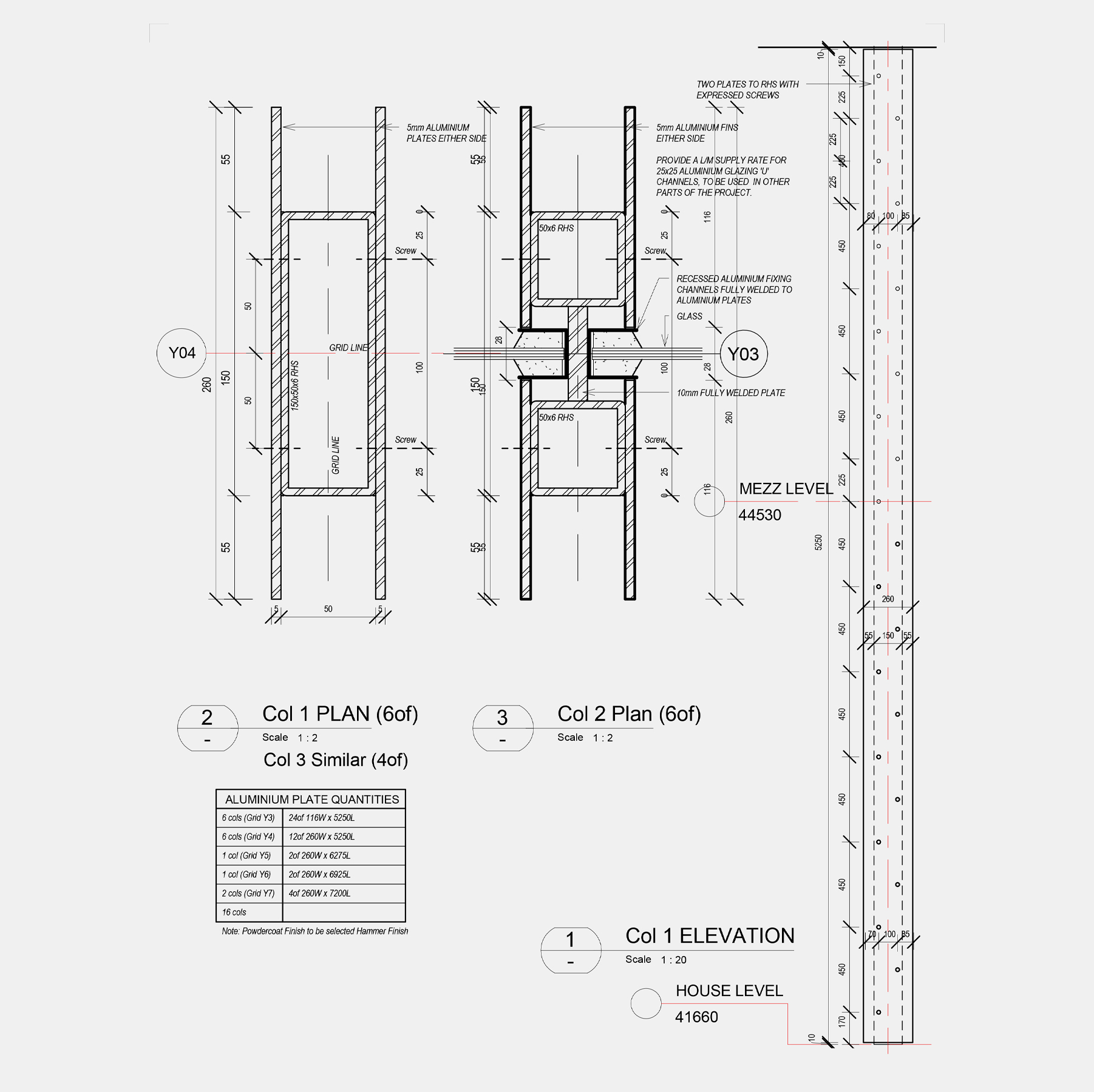
Column Detail
03_2 (a)
Column Detail
Primary Detail Composite column design provides inherited structural strength with a 50mm wide profile spanning up to 8m. Rebate accommodates key conditions.
03_2 (b)
Column Detail
Condition 1 Rebate accommodates track for external blinds
03_2 (c)
Column Detail
Condition 2 Rebate accommodates door seals for external steel doors
03_2 (d)
Column Detail
Condition 3 Rebate accommodates glazing channel for all fixed glazing
03_2 (e)
Column Detail
Thin Column final resolution
03_2 (f)
Column Detail
Thin column final resolution with a span of 7.2m supporting roof and other structural elements
03_2 (g)
Column Detail
Construction Thin column integration in curtain wall and perimeter edge in all three conditions. Copper cladding and timber mullions beyond all derivatives of thin column spacing and rhythm
03_2 (h)
Column Detail
Construction Transparency and rhythm behind copper cladding
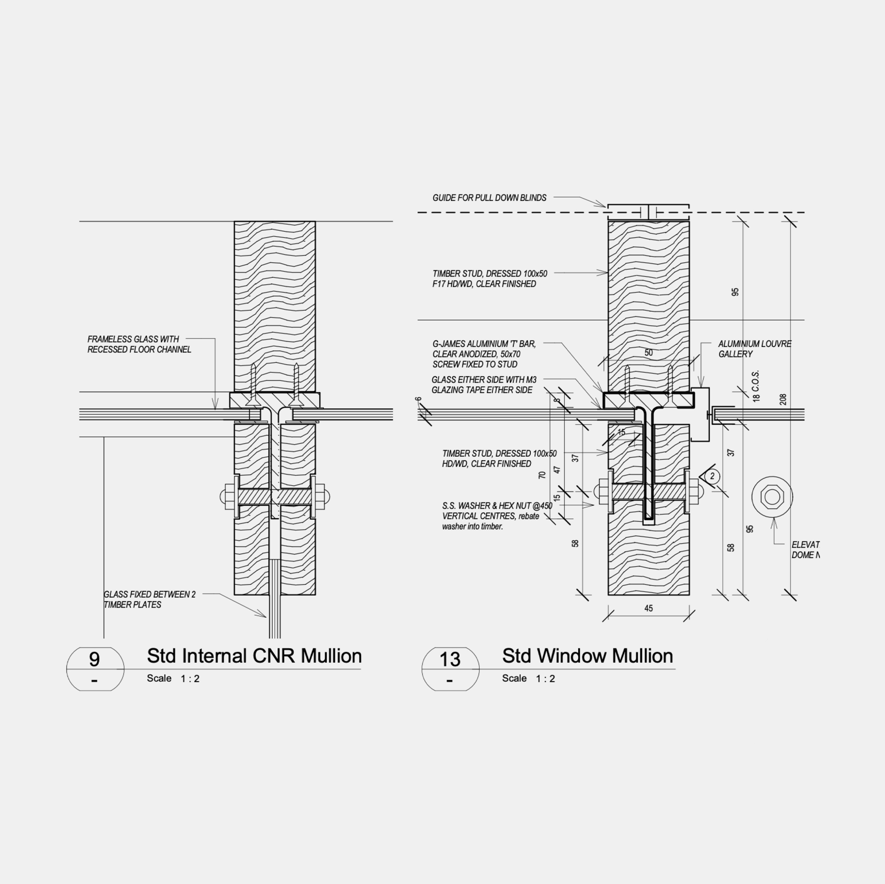
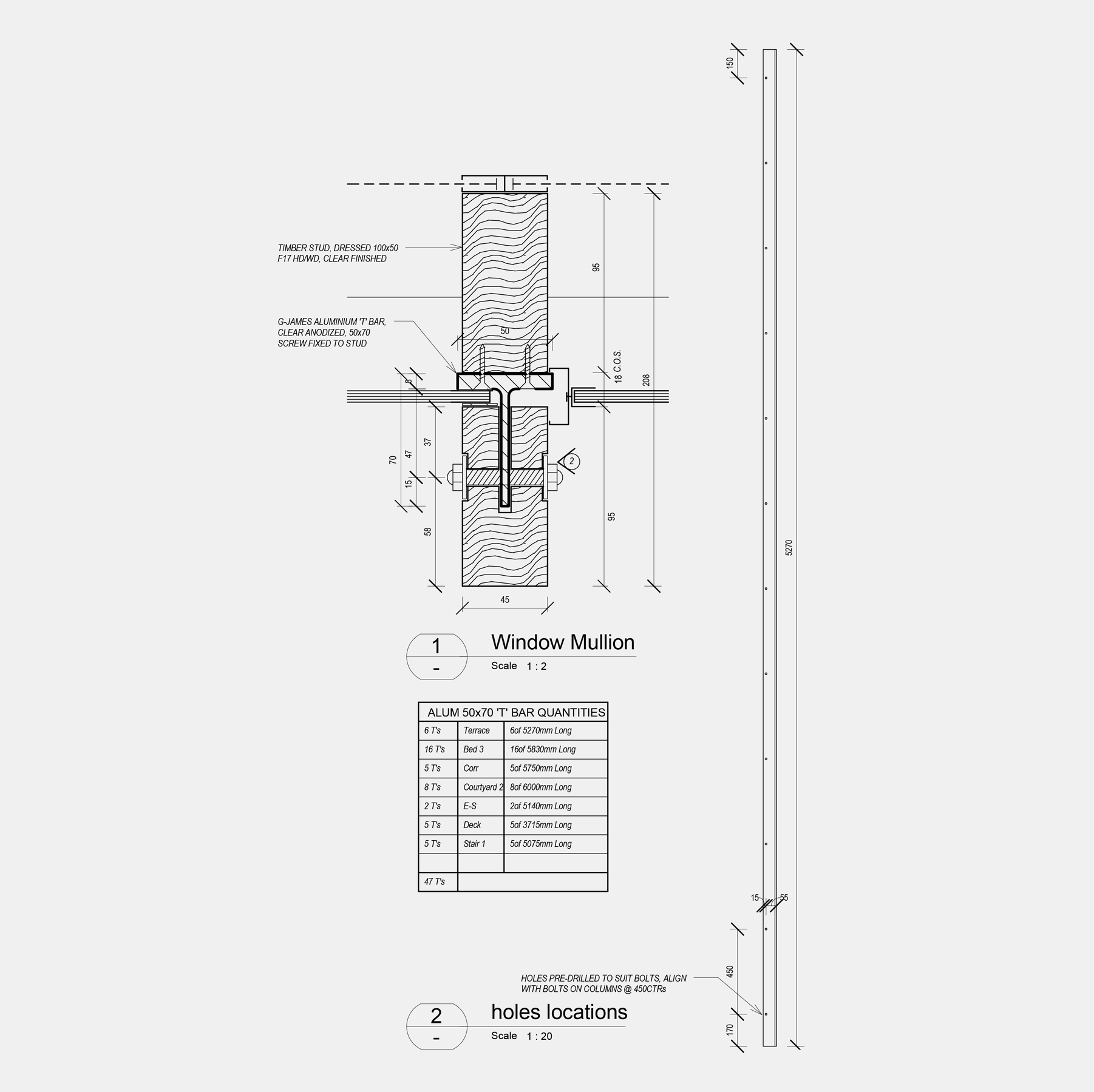
Mullion Detail
03_3 (a)
Mullion Detail
Timber mullions also required to span 5.2m and support intermediate first floor having similar proportions to steel thin columns.
Structural rigidity is achieved in a composite detail using small timber sections (90×42) joined by structural T bar that also provides waterproofing and a continuous surface for structural glazing.
03_3 (b)
Mullion Detail
Timber mullion detail progressed to shop drawings and quantities defined.
03_3 (c)
Mullion Detail
.Construction Mullions in place supporting flooring and ceiling.
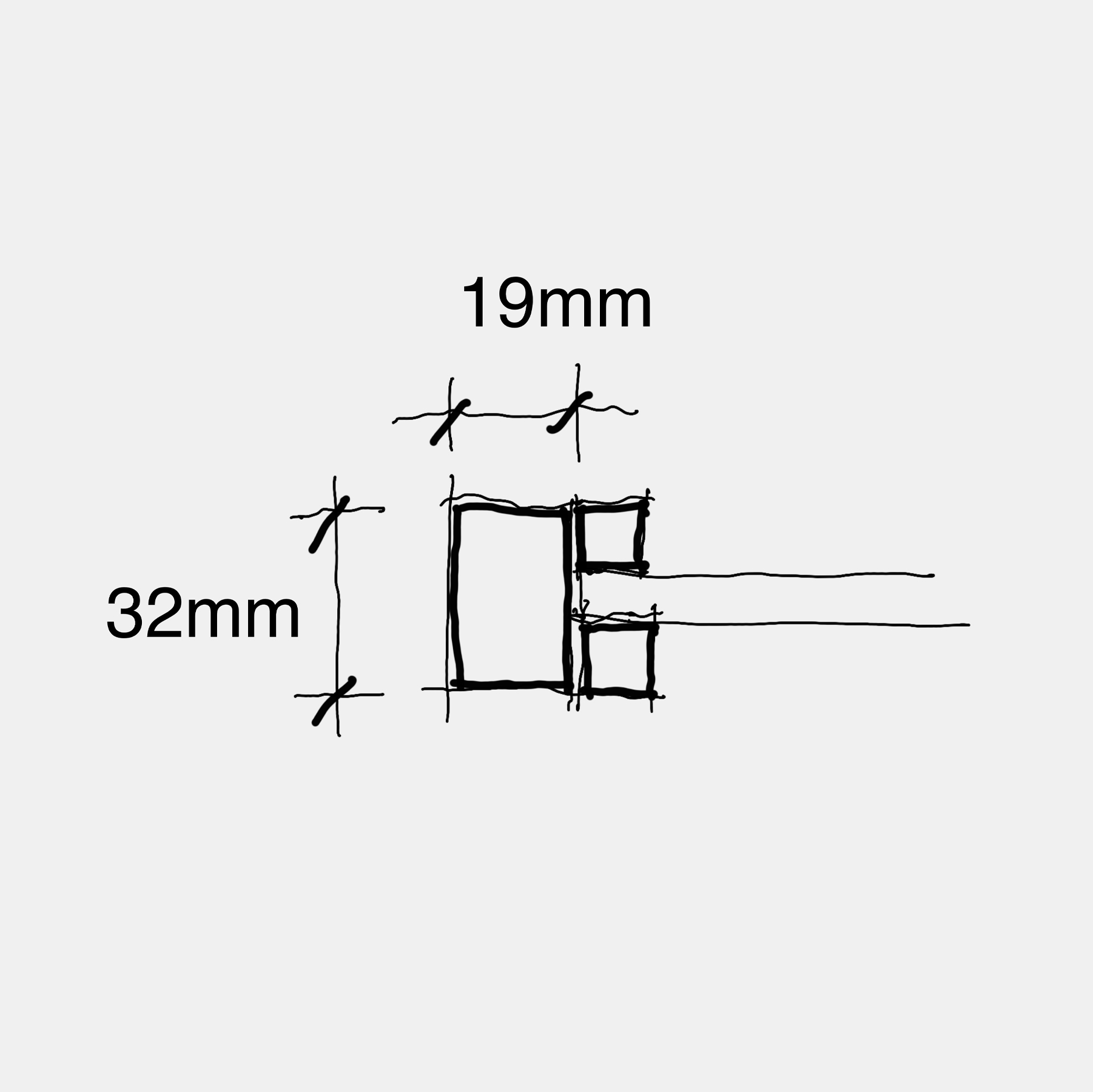
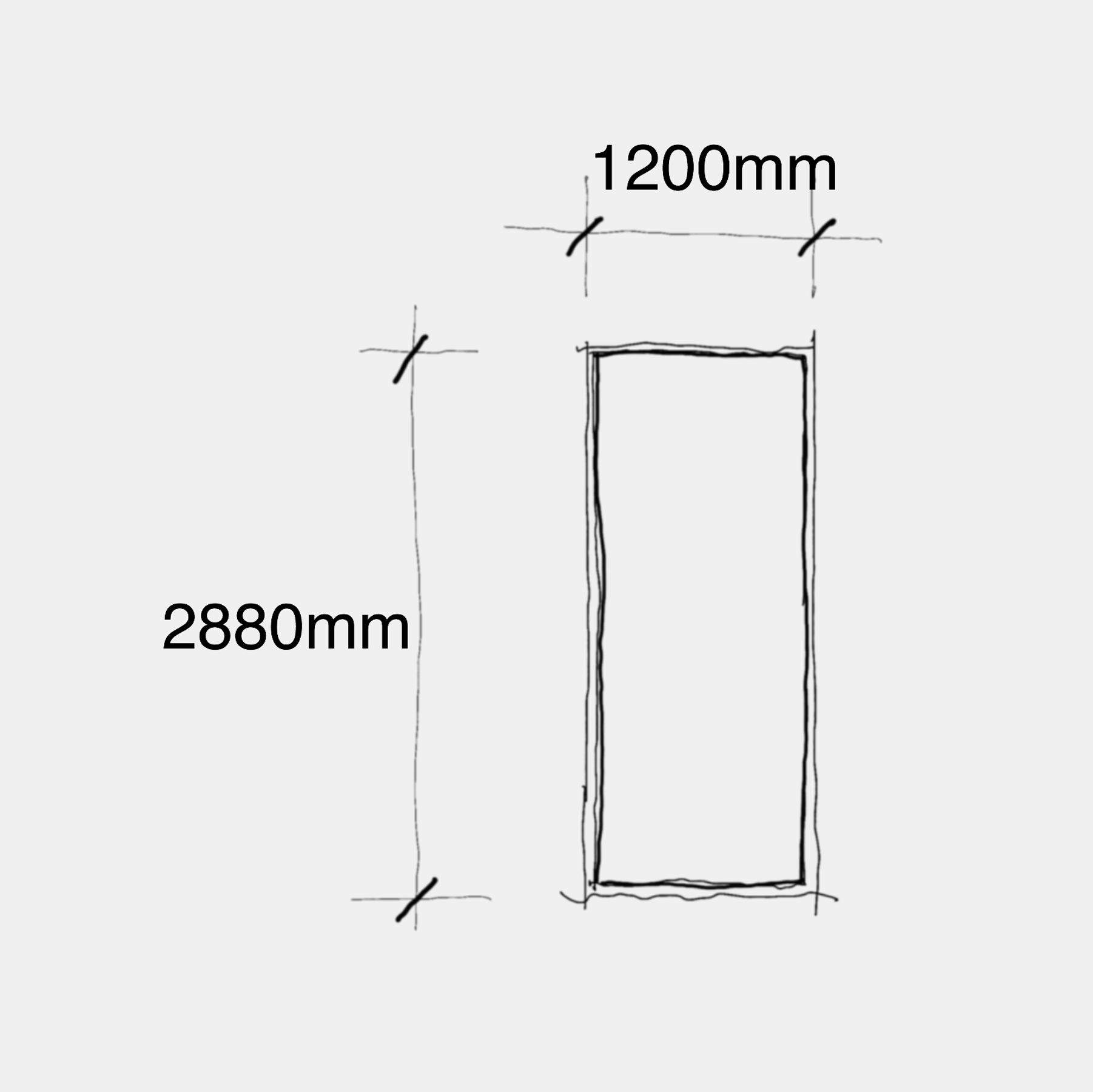
Steel Door Detail
03_4 (a)
Steel Door Detail
Detailing of steel doors was investigated and construction methodology around keeping the framing section to smallest functional denominator providing a minimalist approach that would complement the thin column detail.
Standard solid bar sections where tested and a depth of 32mm was the minimum depth that would accommodate glazing bars (10x10mm).
Material assembles were procured to establish and confirm visually proportions of assembly.
03_4 (b)
Steel Door Detail
The problem to resolve was the very minimalist assembly required to satisfy a significant door size close to 3m high.
03_4 (c)
Steel Door Detail
The detail was resolved by sizing glass to structurally span 2.8mx1.2m. The glass would act as a structural diaphragm or brace (to the thin steel frame surround), the latter being the facilitator for door pivots, hardware and weatherproofing seals.
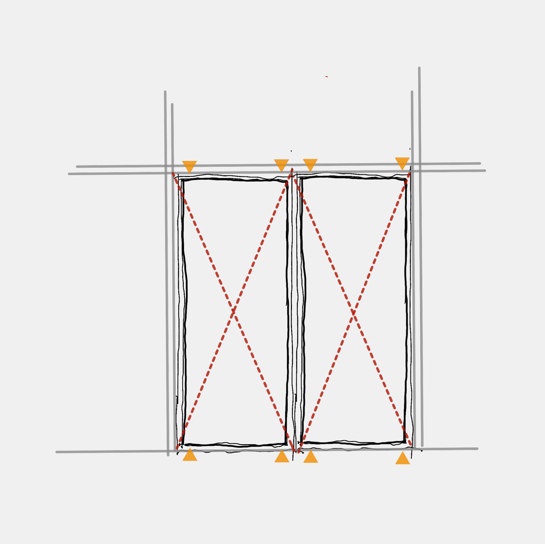
To achieve this, the frames were installed and then braced with wedges so that all doors were square to frames and door gaps consistent all round.
03_4 (d)
Steel Door Detail
The now “plum” frames were structural glazed with wet silicon on both sides creating a structural bond to the glazing bars and frame noting that the glazing bars were welded to the frame on the outside and countersunk fixed to the frame internally.
Once the the structural silicon had cured the framing wedges were removed. The doors remained square and plum with the minimal door frame detail.
03_4 (e)
Steel Door Detail
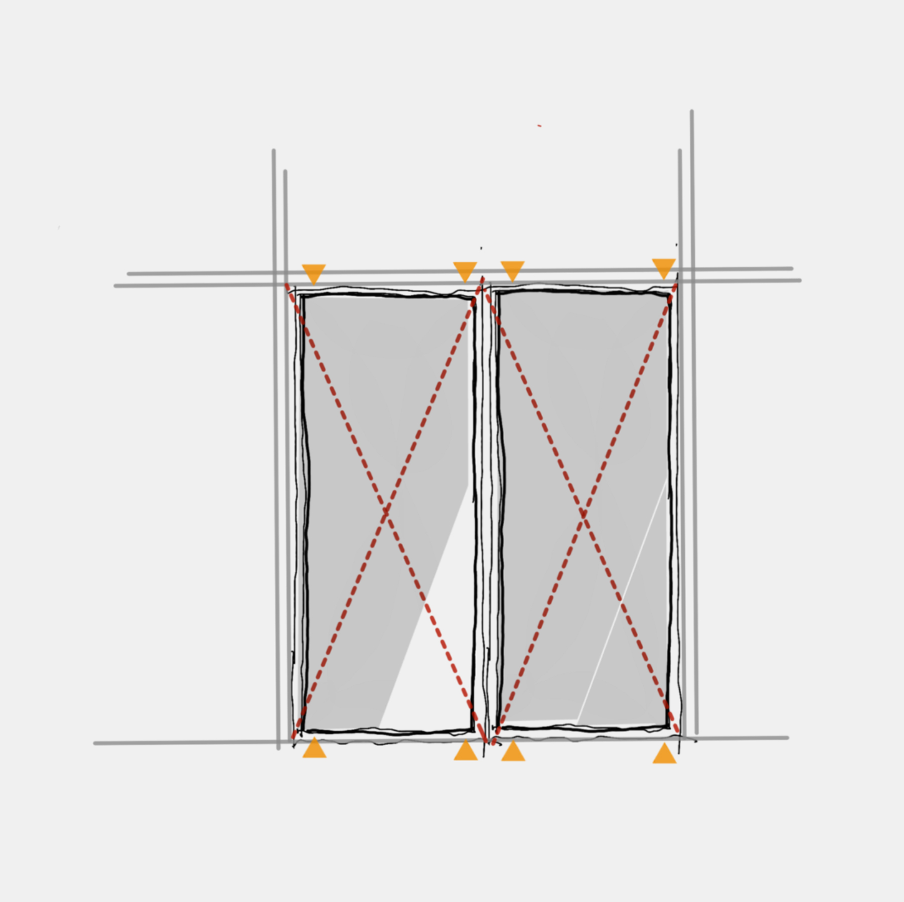
Minimalist custom hardware was integrated into the metal door frames.
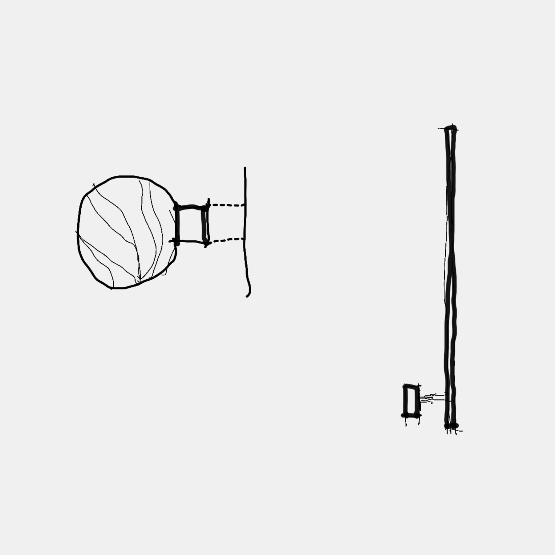
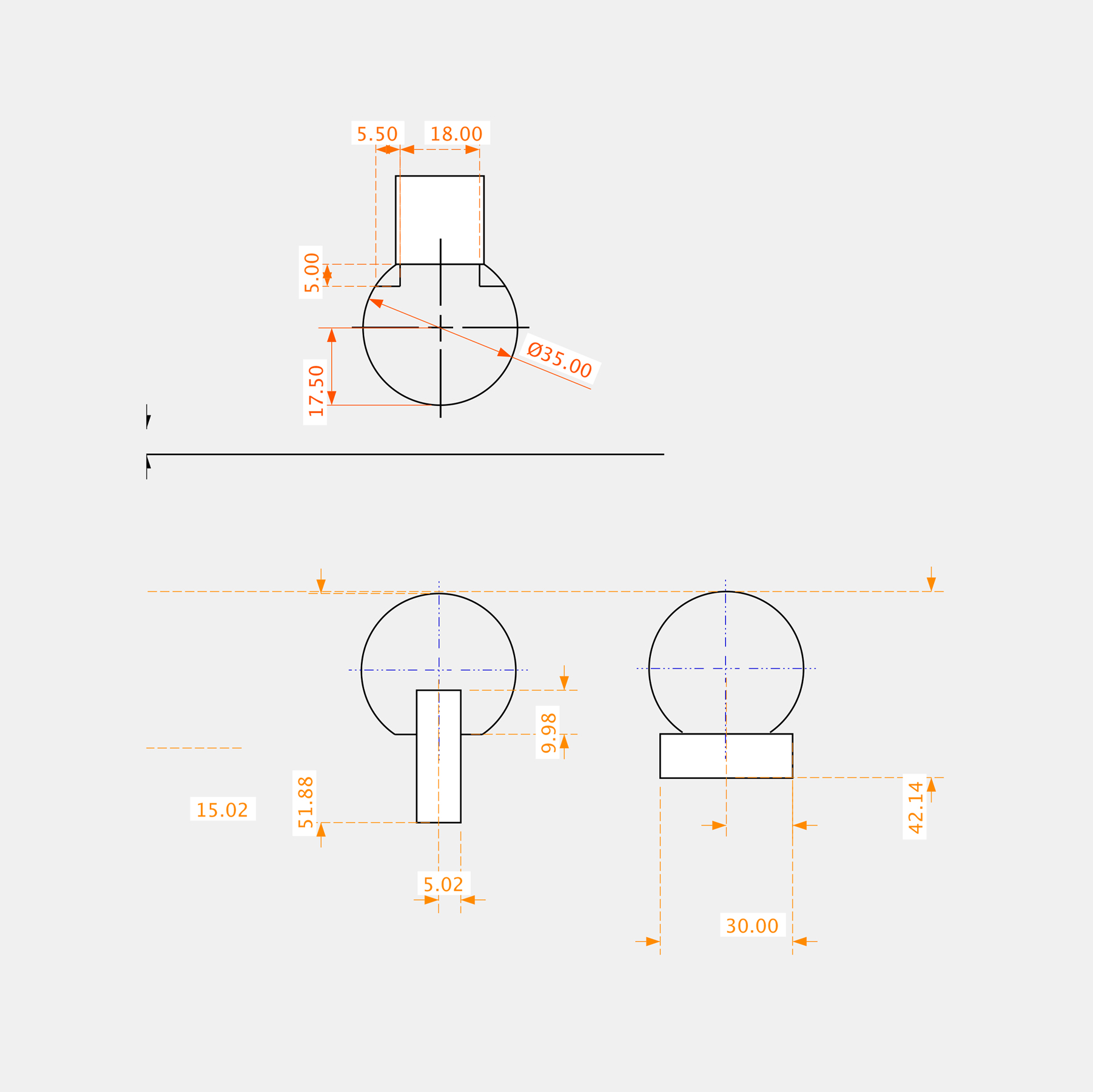
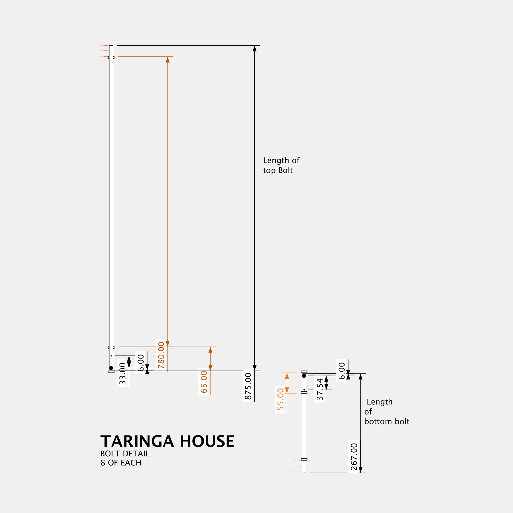
Door handles detailed as 10x10mm bar reinforced by 35mm timber dowl allowing the handles to span the full 2.88m height of the door. Due to the height of the doors very long barrel bolts (1.2m) made from 6mm stainless stee rods were integrated in very simple connectors pre-welded to the frames.
Barrel bold handles were designed and turned (lathe) from solid stainless steel.
03_4 (f)
Steel Door Detail
Door handle detail becomes common language for all handrails in the project.